1-800-355-2335 |
Mon-Fri: 7:30am - 4pm EST |
Contact Us
How to Install Chain Link Cantilever Gates
Shop: Cantilever Slide Gates | Cantilever Slide Gate Hardware | Cantilever Slide Gate Kits
PDF Version: Cantilever Gate Installation Manual (PDF)
Before You Begin:
Step 1 - Obtain necessary zoning and building permits. There may be local zoning or deed restrictions pertaining to height and type of fence and/ or gate. Check out property line setback requirements. Find surveyors pins if the fence is to be located near property lines or have the lot surveyed.
Step 2 - Measure fence footage and locate gate placement.
Step 3 - Call 811 before you dig. Notify your local or state utilities protection service to locate potential buried utilities. There is usually no charge to locate utilities, however a hefty charge could exisit for repairing buried utility lines, not to mention a potential injury to yourself.
Step 4 - Purchase your Chain Link Fence, Cantilever Gates, and Cantilever Gate Hardware from HooverFence.com.
Receiving Products
Check to make sure you have received the proper parts within 5 days of receiving your Hoover Fence Co. cantilever gate kit using your packing list enclosed with your shipment and a copy of your order.
Layout of Project
Tools for Layout:
- Measuring Wheel
- Tape Measure
- Sledge Hammer
- Stakes
- Masonary String
- Marking Paint
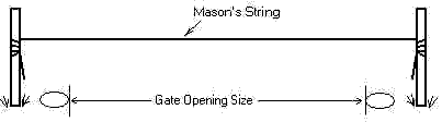
Figure A
Step 1 - Drive two wooden or steel stakes into the ground to be used to attach string line to (Fig. A). Drive stakes a foot or two away from where you want gate posts to be located; this will allow you to drill/ dig holes without obstructions. It may also allow you to 'drop' the string line while excavating holes. Be careful not to bump or move stakes.
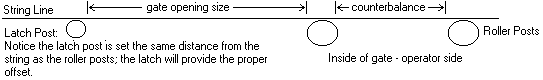
Figure A-1
Step 2 - Stretch masonry guide string tight between these stakes; be sure the string is on the same side of each of the stakes when wrapping. This string will represent the location of the gate and serve as a guide string as you set posts. Posts will be set in concrete 1/8-1/4" from string line even though the gate & latch posts could be of differing diameters (Fig. A-1).
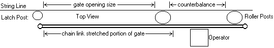
Figure A-2
Step 3 - The gate hardware is designed to make up the difference and cantilever gate latches will compensate for the offset the rollers/ posts cause. Keep in mind, once the rollers are mounted the gate will actually slide a few inches on the inside of these posts and on the inside of the fence (Fig. A-2). This is several inches from the string line.
Make sure the masonry string is tight and free of obstructions. Adjust stakes and string line if necessary. If you remove the string to excavate holes, take care to restretch the string line back the way it was prior to removing.
Setting Posts
Tools for Setting Posts:
- Post Hole Diggers
- Auger
- Shovels
- Spud Bar
- Level
- Concrete Mix

Figure A-1

Figure A-2
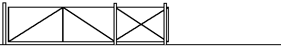
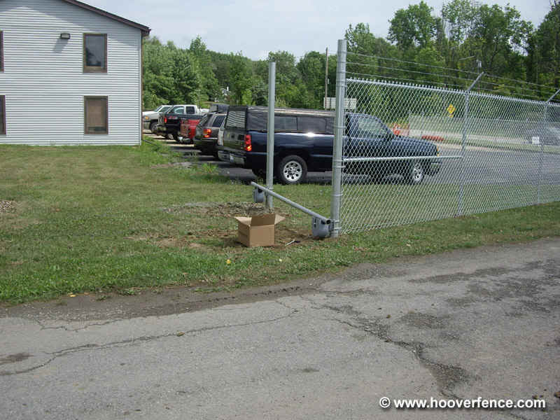
Cantilever gates typically require three posts which make them unique; two are used to mount the rollers and gate and a third is required as a latch post. The two roller posts will be the same size and typically larger than the latch post. Important: although the latch post is smaller in diameter, you will set it in concrete the same distance from your guide string as the roller posts. The cantilever latch makes up for the offset once the gate is installed. Cantilever gates only have chain link stretched on the 'opening' portion of the gate. The portion of the gate which is stretched with chain link is typically 6" more than the 'opening' to provide security where the rollers will offset the gate. The counterbalance is not stretched with chain link as it is typically behind the rest of the fence. Set your gate posts according to the 'opening' size of the gate you've ordered. In example, a 20' wide 'opening' size gate opening should have exactly 20' from inside to inside of the latch post and first roller post Fig A-1. If you must error, error on the small side by setting posts too close together. Since the gate overlaps the opening, posts set to close together will not make much difference.
Cantilever gates are large and heavy as are their posts. Consult local building practices and codes for proper depth and diameter of holes and concrete footings. In general, footers should be three times the diameters of posts installed. The depth for fence post footers is often recommended to be 1/3 it's length and below frost. You can further anchor posts and concrete footers by digging the hole diameter larger at the bottom of the hole compared to the top. This will result in a 'bell-shaped' hole in contrast to a 'carrot-shaped' hole.
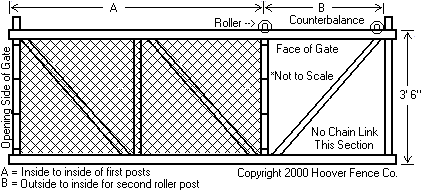
Figure A-3
For locating placement of the last roller post, you'll need to measure the stretched portion of your gate and counterbalance to confirm proper fit Fig. A-3. In general, the stretched portion of the cantilever gate is 6" more than the opening to assure it overlaps any gaps caused by the offset of the rollers. Hardware varies therefore it is always best to take measurements once you receive your gate to plan installation.
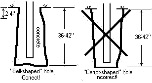
Figure A-4
To set gate posts, dig holes 12-30" in diameter and 42-48" deep. The depth and diameter of the concrete footers vary depending on your location. The hole size above works well in areas with freezing ground. Holes should be "bell-shaped" not "carrot-shaped" Fig. A-4. Next, fill hole(s) with concrete and "stick" the post into the wet concrete and plumb post with a level. Make sure your concrete consistency is not too wet or soupy. Concrete should be of a plastic-like consistency, dry enough so the post will not sink to the bottom of the hole. The gate post should NOT extend to the bottom of the hole; there should concrete under the post as well as all around it. You will want to leave the concrete level approx. 2-4" below grade or the ground level especially in areas which freeze, back fill with dirt. Replumb post. When the ground freezes it can cause the concrete footer to "heave" if you fill the concrete to the top of the hole. Leave the post(s) alone for approx. 24 hours or a sufficient amount of time for the concrete to harden.
Install Cantilever Rollers and Covers
After the concrete has hardened, you may install the two bottom cantilever rollers to the two roller posts, one per post, using provided U-bolts. Install the roller on the highest grade first if terrain is uneven. Care should be taken that cantilever rollers are not installed too low where snow, ice, and freezing ground could impede performance. A straight uniform length of tubing, or pipe may be used to level the second roller to the first by placing it across the top of the rollers. Firmly tighten all nuts on cantilever roller U-Bolts.
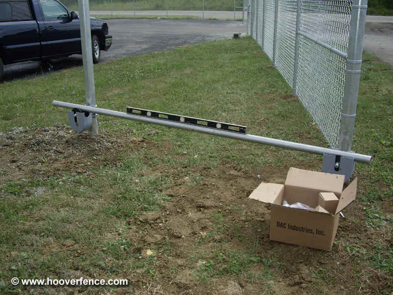
Install cantilever roller on highest grade first.
Install second bottom slide gate roller level with first.
Tighten bottom gate rollers securely.
There are many options for cantilever rollers and covers available in our Cantilever Gate Hardware Catalog. Below are a few examples of the options available.
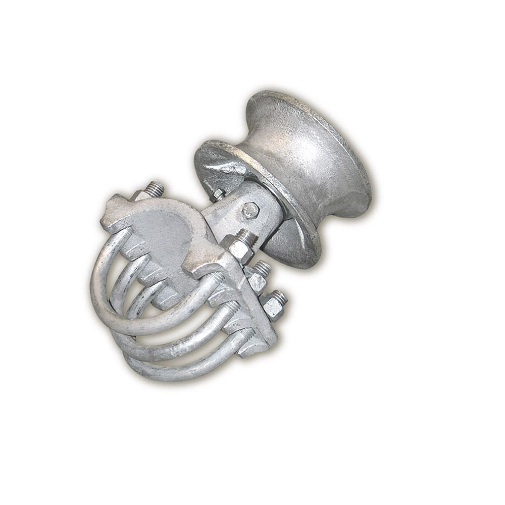
Steel Cantilever Roller
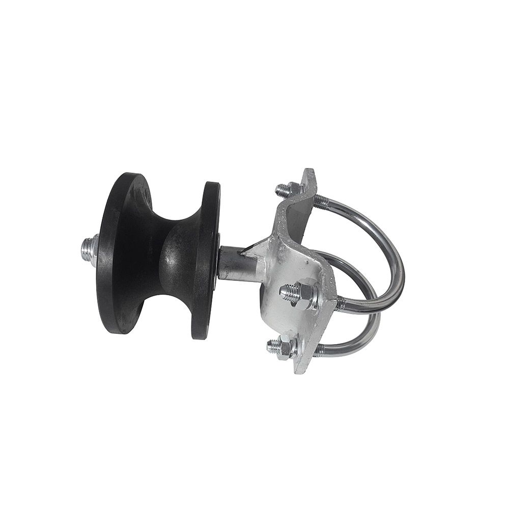
Nylon Cantilever Roller
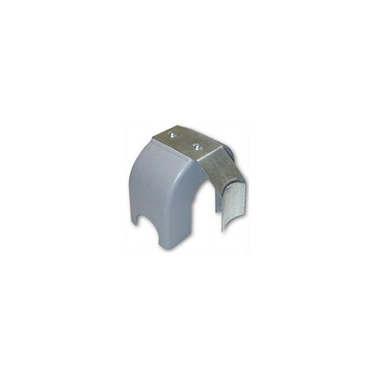
Cantilever Roller Cover
Steel Rollers - Steel cantilever rollers are available with a grease fitting. Available sizes include 3", 4", and 6-5/8". Steel or nylon covers are available.
Nylon Rollers - Nylon rollers have sealed bearings which do not require maintenance. Nylon rollers are available for square and round stock in many different sizes. Steel or nylon covers are available.
Cantilever Roller Covers - Highly recommended on every single install to protect pinch points and limit liability.
Hang Cantilever Slide Gate
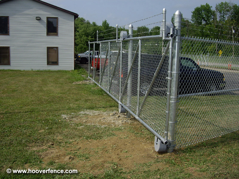
Above: Adjust rollers when cantilever gate is centered, evenly balanced on cantilever gate rollers.
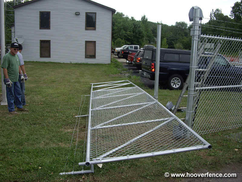
Hanging a cantilever gate usually requires a few extra hands. Start by carrying slide gate to gate roller posts and lying flat on ground behind roller posts face up. Roughly center the entire gate width with the roller posts. With the gate in a horizontal position, rest bottom rail of gate directly on bottom gate rollers.
Next, layout top gate rollers and covers. Depending on make, you may be able to loosely install gate top rollers and covers near the top of roller posts; this allows you to simply slide gate rollers down and into place once the gate is in the upright position. Lift slide gate into the upright position with it's weight centered on the roller posts. Hold firmly or attach safety straps to prevent the gate from falling. Slide top rollers onto gate frame and tighten U-bolts. Allow 1/4-1/2" space between roller and top gate rail to allow for smooth operation and to prevent binding.
Slide gate back and forth a few times to check operation. Make sure cantilever gate is free of any binding that could be caused by rollers being installed too tight to the gate frame. Check gate for level installation. Check all U-Bolts are securely tightened.
Bottom rollers must be level and securely fastened before lifting slide gate into upright position
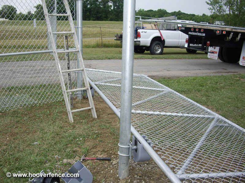
Center gate on bottom rollers before lifting upright.
When installing top rollers, allow a small space of 1/4-1/2" between rollers and top gate member.
Firmly tighten all nuts to U-bolts and adjust covers to prevent rubbing.
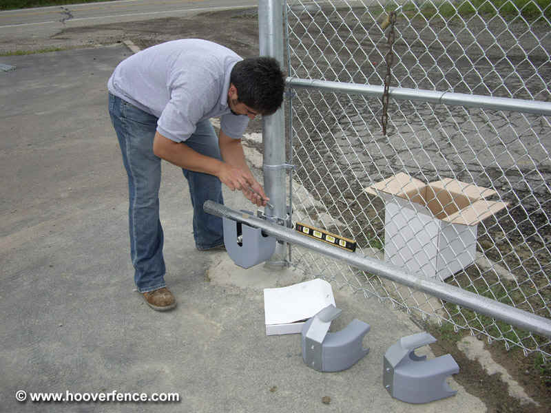
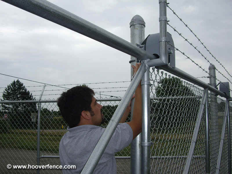
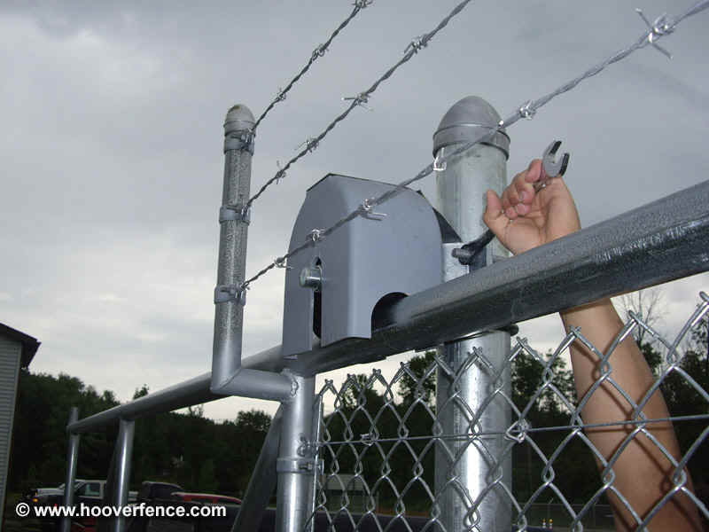
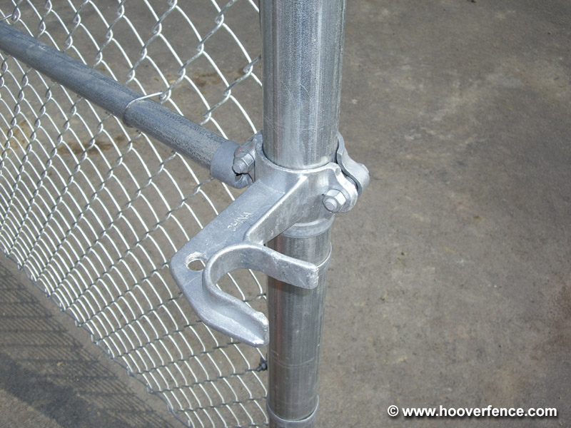
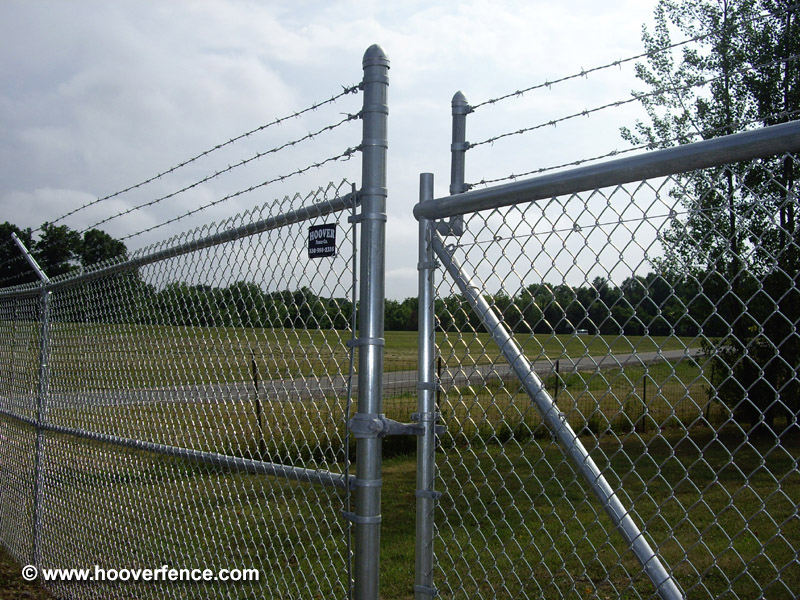
Install Cantilever Slide Gate Latch
The next step is to install the cantilever slide gate latch. Most cantilever slide gate latches are unique in that the 'fork' portion of the latch, or receiver of the latch, is installed on the gate latch post, not the gate. The smaller portion of the latch is then installed to the leading edge of the slide gate. When the two meet, the latch is padlockable. Cantilever gate latches simply install with nuts and bolts. Choose and install at a convenient height.
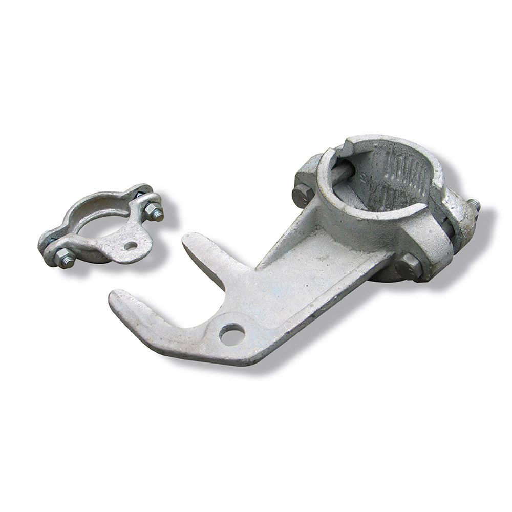
Standard Cantilever Gate Latch
Close-Up of Standard Cantilever Gate Latch
Standard Cantilever Gate Latch in Latched Position
Install Slide Gate Operator
The process for installing a slide gate operator varies depending on which make and model you will install; carefully read instructions with your gate operator thoroughly before proceeding. Following are some general guidelines that apply to most makes of gate operators, however your installation manual will be your definitive resource during installation.
Most slide gate operators will allow for a post mount or pad mount design. Post mounted gate operators usually mount to round or square steel posts which are embedded in concrete footers below frost. The gate operator is 'sandwiched' by these posts and attached with bolts. Most gate operators also allow for a pad mount installation which means the gate operator will rest on a concrete pad. In either case, the first step is usually to set the gate operator posts or pour the pad. Usually the operator will be placed centered between the two roller posts. A chain is attached to the leading edge, or latch side of the gate and extends clear to the opposite end. Brackets will attach to the uprights of the gate and the chain will insert with lock pins.